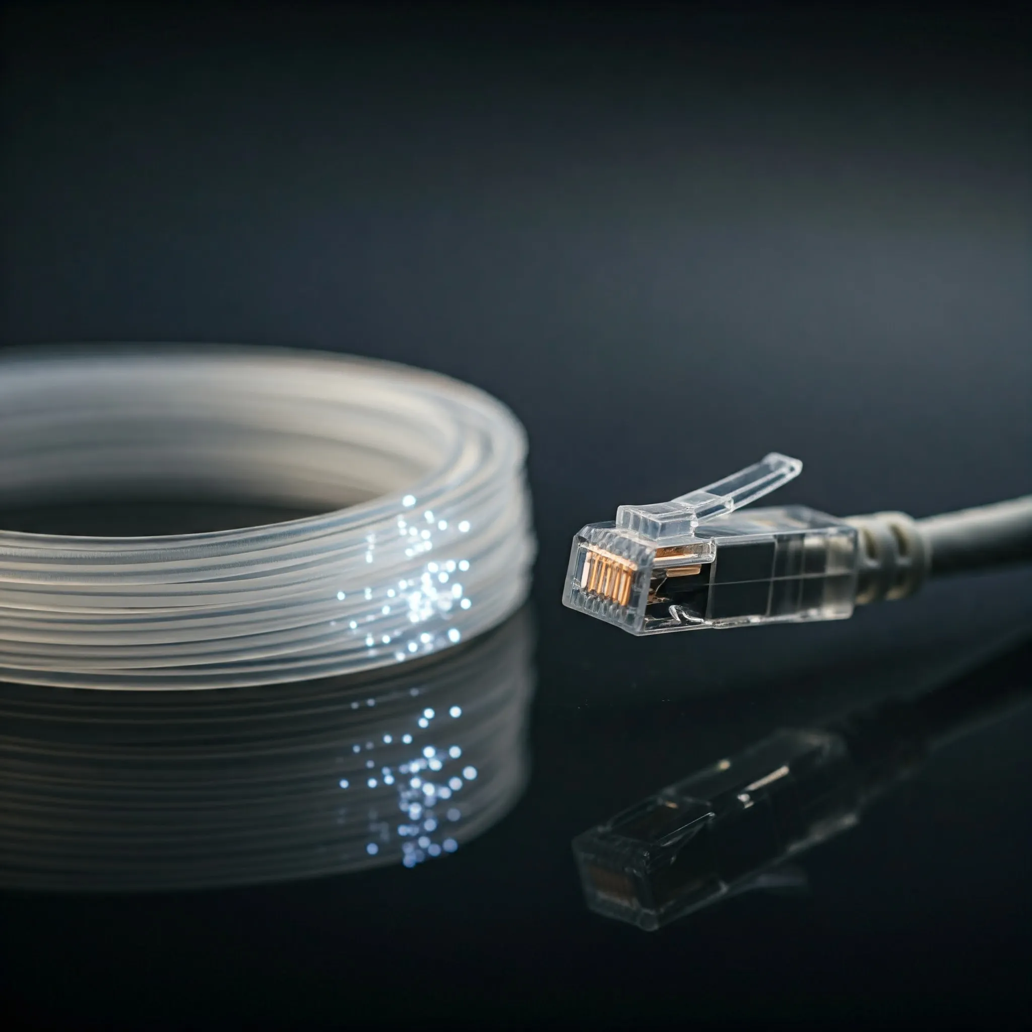
Power over Ethernet, or PoE, carries electrical power and network data through an Ethernet cable. It can simplify installing a compatible camera, access point or desk phone where there is no convenient power socket. The power source still needs electricity; PoE moves that requirement to a switch or injector rather than making it disappear.
Why Use PoE?
A single cable can make device placement neater and more flexible. An access point can sit where coverage is useful, while a camera can occupy the position required for its view. With suitable managed equipment, you can also inspect power use or restart a device by cycling its port. These functions depend on the switch: not every PoE product offers remote management or monitoring.
Central power also makes backup planning easier. A UPS feeding the switch can keep compatible devices powered during an outage, subject to its capacity and runtime. The router, recording server and any other required equipment need backup power too. A powered camera is not much use for recording if the recorder has stopped, and local power backup does not ensure the ISP remains available.
Understand the Power Source and Device
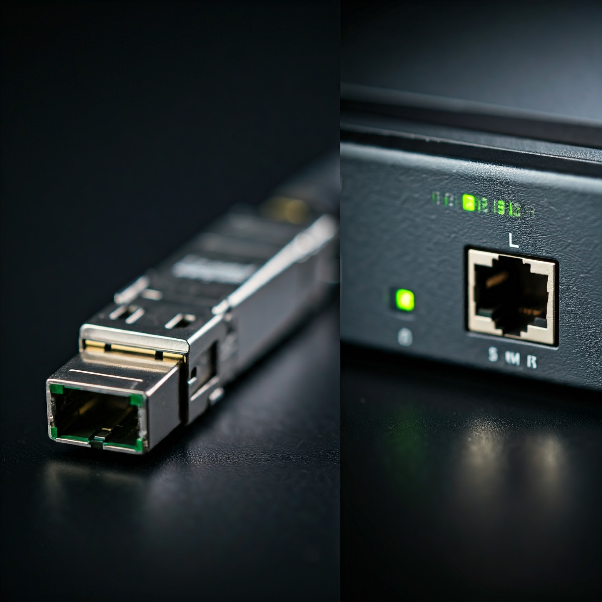
PSE means Power Sourcing Equipment: typically a PoE switch or an injector. PD means Powered Device: the equipment accepting that power. A switch with ordinary data-only ports can feed a suitable injector, which adds power to the outgoing connection. An injector is useful for one device; a PoE switch can make several connections easier to manage.
Check the exact port rather than assuming every port on a PoE-labelled switch supplies power. Also distinguish an injector from a splitter. A compatible splitter takes power from PoE and presents a separate output for equipment designed to use it; its voltage, connector, polarity and power rating must match the target device. The presence of an RJ45 socket alone does not establish PoE support.
PoE Standards and Available Power
The important distinction is between power supplied at the source and power available at the device after cable losses. The following common upper class figures are useful for planning. They are not a promise that every product bearing the same general PoE label supplies that amount.
| IEEE standard/type | Common upper power at source | Power available at device input |
|---|---|---|
| 802.3af, Type 1 | 15.4 W | 12.95 W |
| 802.3at, Type 2, commonly PoE+ | 30 W | 25.5 W |
| 802.3bt, Type 3, Class 6 | 60 W | 51 W |
| 802.3bt, Type 4, Class 8 | 90 W class figure | 71.3 W |
Manufacturers sometimes use 100 W or other high-power marketing labels. Read both the supported standard/class and the device-side specification; a large source figure does not mean that much power reaches the application. “PoE++” and “UPOE” should not replace checking the actual IEEE compatibility and power requirements.
Higher-power four-pair operation uses all four twisted pairs for power. Lower-power Type 3 classes also exist, so not every Type 3 connection is a 60 W load. Power and data share the cable without requiring you to reserve spare pairs from Gigabit Ethernet. Do not split a cable's pairs between improvised devices to try to create extra connections.
Standards-Based and Passive PoE
Standards-based PoE checks for a compatible powered device before applying operating power, then uses classification and related power-management mechanisms. Under normal operation with compliant equipment, a non-PoE computer can use a standards-based port as a data connection. That is different from claiming all hardware or damaged cabling is one hundred percent safe.
Passive PoE does not perform the same compatibility negotiation. It may supply power continuously at a specified voltage and pin arrangement. Some wireless equipment deliberately requires passive power, but an unmatched injector can damage another device. Verify the manufacturer's exact voltage and wiring requirements; do not identify compatibility from the word “PoE” or connector shape alone.
A passive-to-standard converter must itself be appropriate to both sides. If the documentation is unclear, establish the requirement before connecting equipment. Do not try a sequence of random injectors as a troubleshooting method.
Calculate the Total Switch Budget
A per-port rating is separate from the total power available across the switch. Eight ports capable of 30 W each do not necessarily mean a 240 W PoE budget. The power supply rating may also include the switch's own consumption, so use the published PoE budget, not simply the number printed on its mains adapter.
For an illustrative budget, suppose the source-side allocations are 18 W each for two access points and 8 W each for four cameras. The total is 2 × 18 + 4 × 8 = 68 W. A 60 W PoE budget cannot cover that allocation. If you choose a planning allowance of twenty percent, 68 × 1.2 = 81.6 W; select equipment that meets the needed allocations and has room for future changes. That allowance is a planning choice, not an IEEE requirement or a measurement of those hypothetical devices.
Use maximum required or allocated power, including heaters, infrared lights and other peak functions. Classification may reserve more power than a device's idle reading. Check how the switch handles shortages: it may deny a new device or remove power from lower-priority ports. TP-Link documents that priority behavior on specific models, rather than promising every overloaded switch will fail in the same way.
Cabling and Data-Rate Checks
Power delivery and Ethernet speed are separate specifications. A PoE+ switch can have 100 Mbps ports; a newer access point may need Gigabit or multi-gigabit data as well as suitable power. Check the injector's data capability and each uplink in the path before assuming the power upgrade also increases throughput.
Use standards-compliant copper cabling suitable for the installation. Fluke's guidance identifies copper-clad aluminium as a concern because higher resistance means more heating and lower voltage at the powered device. Connectors, termination quality, cable length and bundled-cable conditions matter as well. Choose outdoor-rated equipment and appropriate protection for outdoor routes instead of assuming an indoor switch and cable are suitable everywhere.
A Practical Selection and Verification Checklist
- Record each device's exact model, supported power standard, maximum requirement and required Ethernet rate.
- Match the source's per-port capability, total PoE budget and compatible cabling to those requirements.
- Check whether management, port priorities and power monitoring are available if you need them.
- Connect one device first using a known-good cable and inspect its power/link status.
- Test peak functions and normal simultaneous use, then add the remaining devices while watching the total allocation.
- Label ports and keep a record of requirements so future replacements do not introduce incompatible power equipment.
If a device repeatedly restarts, check power allocation, cable condition, port logs and peak features before blaming its software. A device with adequate power can still have a network configuration problem; a data link alone does not prove that every power condition is satisfied. PoE is a convenient way to streamline a network when these practical limits are understood.